What is a Speaker Crossover?
A speaker crossover is a technology used in audio production to optimize speaker system performance by sending each speaker only the frequencies it is designed to accurately reproduce.
The function of a speaker crossover is to divide a full-range audio signal into its high, mid, and low frequency components and to distribute each frequency band to the loudspeaker driver best-suited to reproduce it.
Speaker crossovers are implemented using either circuits enclosed within speaker cabinets or processing before the input of a power amplifier.
A speaker crossover is a technology used in audio production to optimize speaker system performance by sending each speaker only the frequencies it is designed to accurately reproduce.
If you are designing a sound system, the first step should be to roughly determine the placement of the speakers and the second step should be to choose your speakers. I’ve created two guides that will clearly walk you through the common rules for speaker placement and the most important speaker specifications to consider when choosing speakers. Download the Speaker Placement Guide and the Speaker Specifications Guide if you’d find that helpful.
When Are Speaker Crossovers Necessary?
Speaker crossovers are used in a variety of situations, in which multiple speaker drivers work together to produce a full-range audio signal.
Many sound systems contain multiple speakers. Based on its size, shape, and design, each speaker is responsible for accurately reproducing a specific range, or band, of frequencies. Using a crossover allows control over which frequencies are sent to which speakers, so that all speakers in the system work together to achieve the best possible sound quality.
Sending a full-range signal to all speakers within the system, regardless of each speaker’s design, can be problematic. Firstly, each speaker is only capable of accuracy within a limited range. Sending frequencies outside of this range will waste the resources available to the speaker and yield inaccurate results. Additionally, low-frequency energy can cause damage to a high frequency driver.
Types of Loudspeaker Drivers
Subwoofer
Subwoofers are loudspeaker drivers designed to reproduce low frequencies.
To efficiently reproduce low frequencies, a large volume of air must be moved. This requires a speaker with a large diaphragm area and long diaphragm excursion. In other words, low frequency drivers are large speakers capable of large movements. Subwoofers can generally reproduce frequencies in the range of 1 Hz to 150 Hz.
Subwoofers are most commonly direct radiator cones, sized at either 12, 15, or 18 inches in diameter.
Woofer
Woofers are loudspeaker drivers designed to reproduce low and mid-range frequencies.
Their design is nearly identical to that of subwoofers, however they are generally smaller and capable of less extreme excursions. Mid-range woofers can produce frequencies in the range of 60 Hz to 6 kHz.
They are direct radiator cones, commonly sized 5 to 12 inches in diameter to allow for more accurate reproduction of higher frequencies.
Tweeter
Tweeters are loudspeaker drivers designed to reproduce high frequencies.
The excursion of a tweeter diaphragm is limited by its physical size. Luckily, to efficiently reproduce high frequencies requires far less diaphragm excursion than is required to reproduce low frequencies. Horns are often used with high-frequency drivers to further reduce the diaphragm excursion requirements.
Tweeters are relatively small electromagnetic or piezoelectric drivers capable of reproducing frequencies beyond 5 kHz.
Common Uses of Speaker Crossovers
There are two common applications of speaker crossovers: multi-way speaker cabinets and multi-cabinet speaker systems.
Multi-Way Speaker Cabinets
A multi-way speaker cabinet is a single enclosure that contains multiple speaker drivers. In this image, you can see a 2-way speaker. This speaker enclosure contains a woofer to reproduce low and mid-range frequencies and a tweeter to reproduce high frequencies.
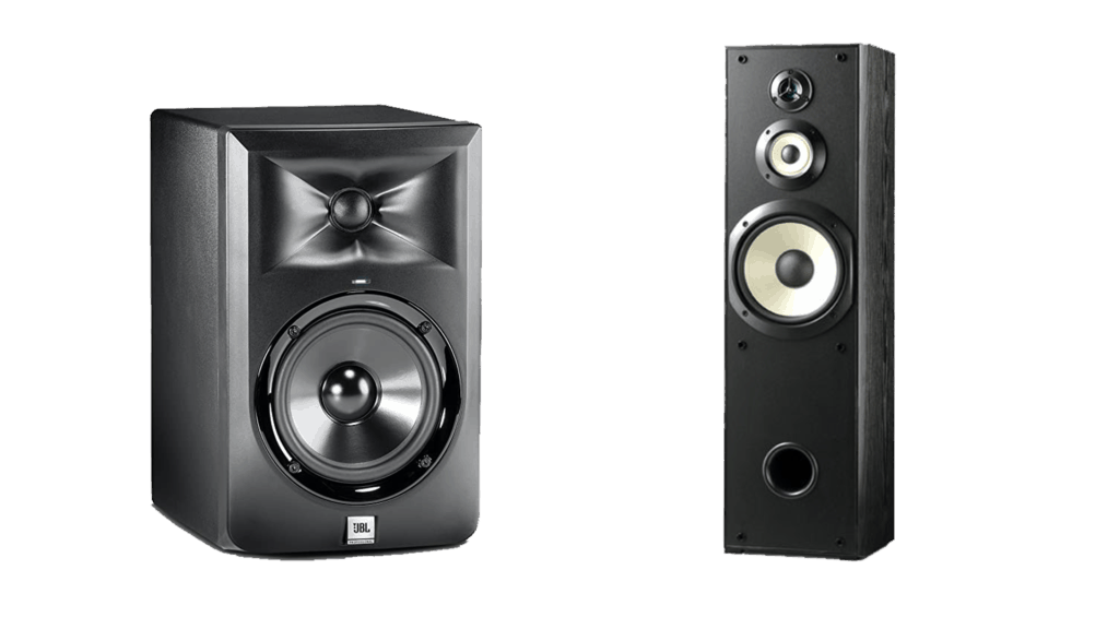
The term, 2-way, indicates that the audio signal is separated into two frequency bands: low-mid and high. The low-mid frequencies are sent to the woofer, while the high frequencies are sent to the tweeter, using a crossover. Another common design is a 3-way speaker cabinet, which might contain a woofer for low frequencies, another woofer for mid-range frequencies, and a tweeter for high frequencies.
It’s important to note that a 3-way speaker cabinet can contain more than three drivers. In many cases, two low frequency woofers are used alongside a mid-range woofer and a high frequency tweeter. The crossover network determines the term used to describe the speaker cabinet.
Multi-Cabinet Speaker Systems
Speaker crossover systems are also used to optimize the sound quality of multi-cabinet speaker systems, in which separate speaker enclosures are used. In these cases, each speaker cabinet is tuned to reproduce a specific frequency band.
A common example of a multi-cabinet speaker system is a system with a stand-alone subwoofer. In this configuration, low frequencies are sent to a subwoofer speaker cabinet which is designed to reproduce only low frequencies. The remaining frequencies in the low-mid, mid, and high ranges are sent to a separate cabinet.
It is very common to combine these two techniques, using a multi-way speaker cabinet for low-mid, mid, and high frequencies and a separate subwoofer cabinet for low frequencies.
Speaker Crossover Settings
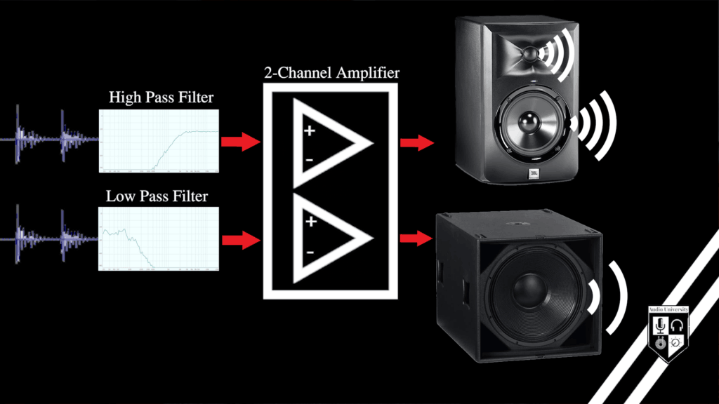
Speaker crossovers are created using audio pass filters. For example, to set the crossover between a woofer and a tweeter will require a low pass filter on the woofer signal and a high pass filter on the tweeter signal. This can be done with electronic components or digital signal processing (DSP).
Low pass filters allow low frequencies to pass while attenuating, or reducing, higher frequencies. High pass filters allow high frequencies to pass while attenuating lower frequencies. To learn more about high pass filters, you can read this article or watch this video by Audio University.
Low pass and high pass filters have two basic control settings: cutoff frequency and slope.
Cutoff Frequency
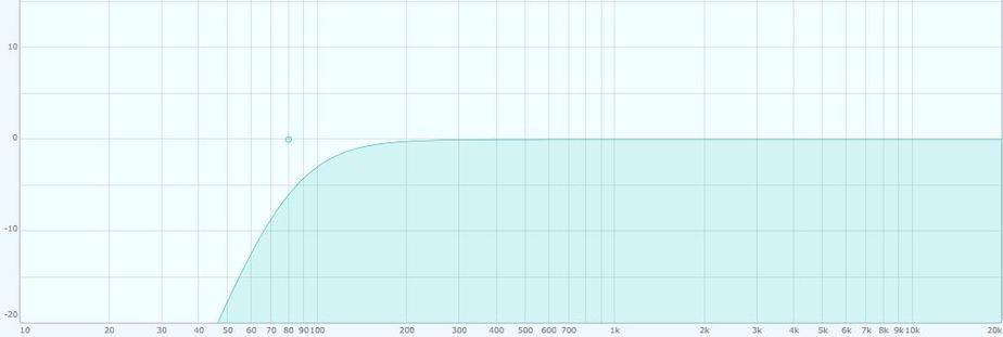
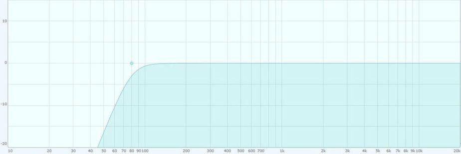
The cutoff frequency of a high or low pass filter will determine at which point the filter begins. In this image, you can see a high pass filter with a cutoff frequency of 80 Hz. The cutoff frequency is usually the point the filter reaches -3dB of attenuation.
Slope
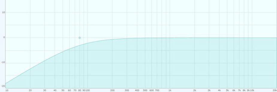
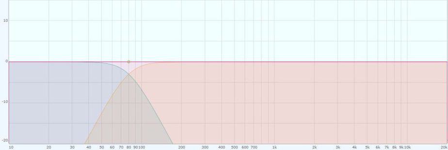
The slope of a high or low pass filter determines the rate of attenuation over frequency. A high pass or low pass filter can be steep or gradual. The following images show a comparison of a gradual filter with a slope of 6dB per octave and a steep filter with a slope of 24dB per octave.
The most common slope settings for crossover filters in professional audio are 12dB per octave and 18dB per octave.
6dB/Octave Slope
24dB/Octave Slope
Crossover Point
As stated above, a crossover system is usually the combination of two audio pass filters, each with a cutoff frequency and slope. Setting the cutoff frequency and slope of both filters will determine the crossover point.
The crossover point is the point where the two filters intersect.
The crossover point that is appropriate for a particular speaker cabinet will be determined by the manufacturer and is usually in the technical specifications, found either online or in the user manual.
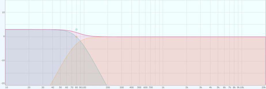
Ideally, the crossover point will be the point when the two filters that make up the crossover intersect at -3dB. This will ensure a smooth frequency response when the drivers are combined.
To better visualize this, look at this graph. Both the low pass filter and the high pass filter have a cutoff frequency of 80 Hz. You can see that there is a -3dB dip at 80 Hz in both the low and high frequency driver’s frequency response. 3dB is one half the power output, which means that when the two drivers add together they will combine to fill the hole. This will theoretically create a straight line across the graph, indicating that all frequencies are equally represented.
Gain
While gain is not technically a setting of the crossover, it is important to understand how it affects the crossover point.
Let’s use the same graph used above. This time, there will be +3dB of gain applied to the low frequency driver only. As you can see, this gain boost moves the crossover point. Now, the lines no longer intersect at 80 Hz, but at a higher frequency.
This is something to consider when setting the amplifier gain in an active crossover speaker system.
Types of Speaker Crossover Networks
There are two types of crossovers used in sound systems: passive and active. This is not to be confused with active and passive speakers. In this instance, “passive and active” describes the method used for implementing a crossover network.
Passive Crossovers
Passive crossovers are placed between the output of the power amplifier and the input of the loudspeaker drivers.
Thus, passive crossovers deal with speaker level signals, which are much more powerful than the line level signals that pass through an audio mixer. When using a passive crossover network, one amplifier channel is used to power multiple drivers.
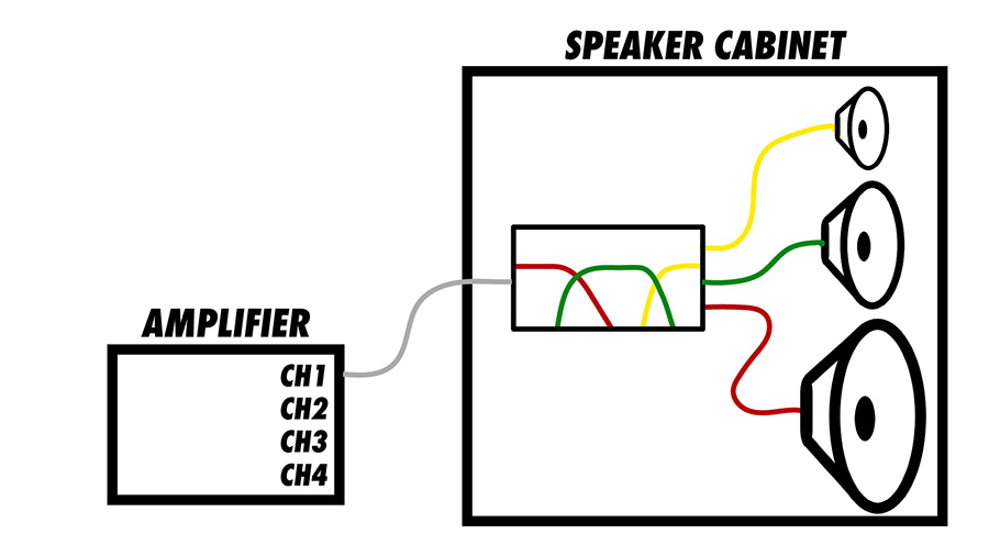
A passive crossover is most commonly enclosed within the speaker cabinet, itself. They are made up of electrical components such as capacitors and inductors. These electrical components divide the signal from the amplifier and distribute the frequencies to the correct drivers. Most passive crossover networks are designed to work with a specific speaker driver.
Active Crossovers
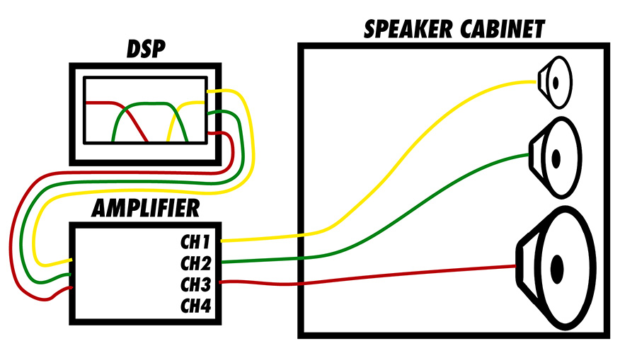
Active crossovers are placed before the power amplifier.
Therefore, active crossovers deal with line level signals. When using an active crossover network, separate amplifier channels are required for each driver or set of drivers.
Systems which include a 2-way speaker powered by two amplifier channels and an active crossover are called biamplified systems. Similarly, 3-way speaker systems powered by three amplifier channels and an active crossover are called triamplified systems.
Hybrid Crossovers
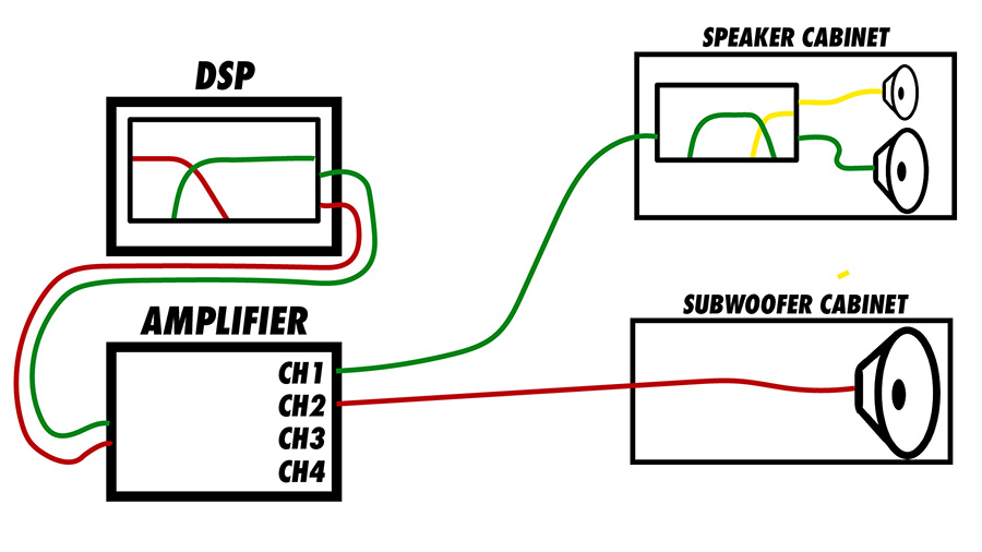
In many cases, both passive and active crossovers are used in a single system.
For example, an active crossover might be used to separate low frequencies from mid/high frequencies, feeding low frequencies to one channel of an amplifier and mid/high frequencies to the second channel.
The first amplifier channel powers a stand-alone subwoofer, while the second amplifier channel powers a 2-way speaker cabinet. Inside the 2-way speaker cabinet, a passive crossover network separates and distributes the mid frequencies to the woofer and the high frequencies to the tweeter.