One of the most powerful ways to prevent noise from entering audio signals is to make balanced connections between devices. Some cables are capable of balanced connections, others aren’t.
In this post, we’ll take a look inside some common audio cables to see how they work. I’ll also explore a widespread misconception about balanced audio and demonstrate how big of a difference balanced connections actually make.
But if this is our first time meeting, my name is Kyle. Welcome to Audio University!
What Is Balanced Audio?
Balanced audio is a method of connecting audio devices that eliminates noise. Any noise picked up by the interconnecting audio cable is equal in both conductors (a common-mode signal), and is therefore cancelled out at the differential input device. To fully cancel noise, both conductors of the interconnecting cable must have equal impedance.
In the following sections, we’ll take a close look at what this means, how it works, and the difference between balanced and unbalanced audio connections.
Why Use Balanced Audio?
There are many ways noise can enter an audio signal chain. One of the most common sources of noise is other electronic devices.
The currents flowing through any electronic device will form a magnetic field that could induce currents onto nearby circuits.
We are really very lucky to have the cable technology we have today to help prevent this noise from ruining our recordings.

Balanced vs Unbalanced: Audio Cable Construction (XLR, ¼-Inch TRS, ¼-Inch TS, RCA)
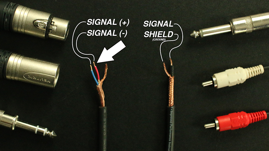
When connecting audio components together, you’ll most likely be using one of these cables: XLR, ¼-inch TRS, ¼-inch TS, and RCA.
Let’s expose the wires in each of these cables to get a closer look at what’s going on inside.
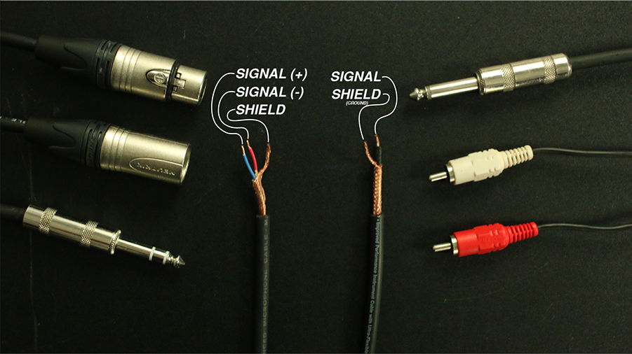
The XLR and ¼-inch TRS cables both contain a shield, a positive, and a negative. The ¼-inch TS and RCA cables contain a positive and a shield (or ground).
The cable construction will be important in order to understand why the first two cables can support balanced connections and the second two cables cannot.
What Is A Balanced Circuit?
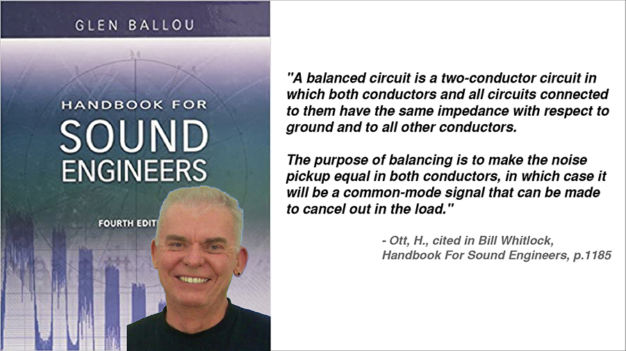
In the book, Handbook For Sound Engineers, Bill Whitlock shares this definition:
A balanced circuit is a two-conductor circuit in which both conductors and all circuits connected to them have the same impedance with respect to ground and to all other conductors. The purpose of balancing is to make the noise pickup equal in both conductors, in which case it will be a common-mode signal that can be made to cancel out in the load.
Ott, H., cited in Bill Whitlock, Handbook For Sound Engineers, p.1185
If I’m being honest, I found this definition kind of difficult to understand when I first heard it. That’s probably because I don’t have a particularly strong background in electrical engineering. You might feel the same way, so let’s try to simplify this definition a bit.
Balanced Audio Explained
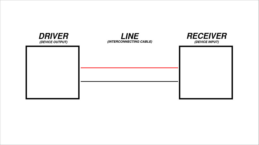
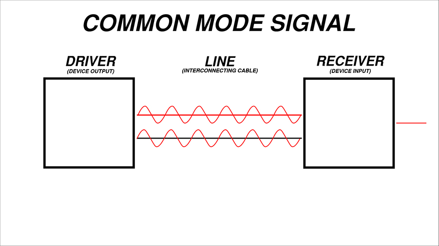
In any circuit, you’ll find a driver (one device’s output), a line (the interconnecting cable), and a receiver (another device’s input).
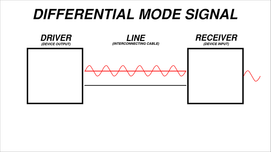
Differential-Mode Signal
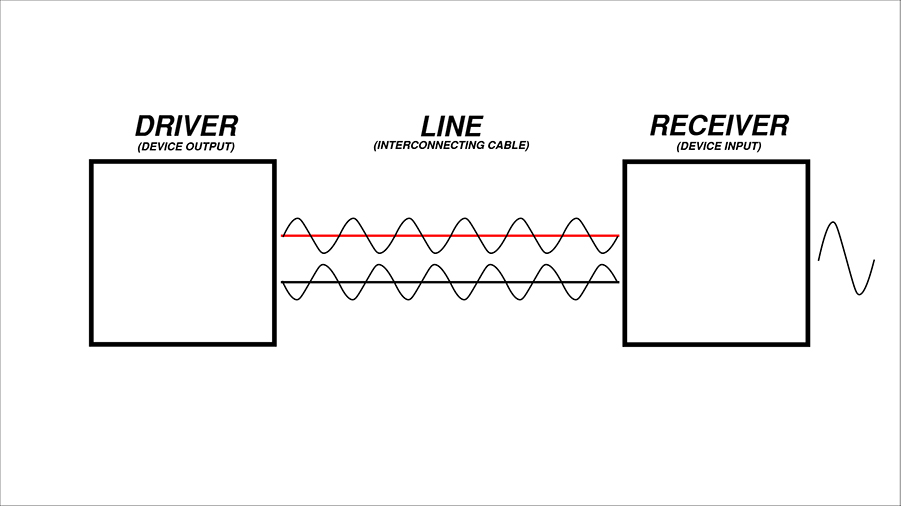
A balanced receiver uses a differential device, which will only respond to the difference in voltage between the two wires of the interconnecting cable.
So, if there is a voltage on one wire and not on the other, the voltage will go through.
This is an example of a differential-mode signal, because there is a different voltage on each wire.
Common-Mode Signal
If there is an identical voltage on each wire, they will cancel out in the differential device.
This is an example of a common-mode signal, because there is a common voltage on each wire. It results in common-mode rejection.
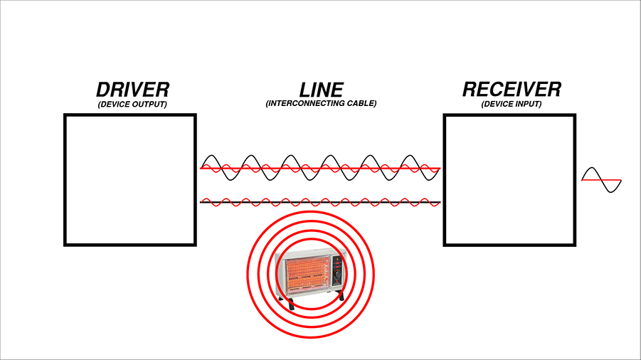
How Balanced Audio Works
This is where it gets really interesting, because we can use this to our advantage!
Imagine an audio signal sent across one of the wires. When it reaches the differential device, it is allowed to pass through.
However, along the way there is some noise from nearby electronics that induces voltage onto the wires. The voltage that’s induced is equal in both wires, so the differential device will completely cancel out the noise!
There are two important details about the cable that make this noise cancelation possible.
First, both wires need to have the same impedance – that way the strength of the noise voltage that is created is equal in both wires.
Second, the wires need to be the same distance from the noise source – again, so that the strength of the noise voltage is equal in both wires.
Looking back at these audio cables, we can see that each of them consist of two conductors. (The XLR and TRS cables do each have a shield, but the shield isn’t relevant to the cable’s ability to form a balanced circuit, so let’s ignore that for now.)
We can clearly see that the wires in the XLR and TRS cables are identical. Given that the impedance of a wire varies based on its size, this suggests that the wires in the XLR and TRS cables have equal impedance.
The wires are twisted in the XLR and TRS cables. This helps ensure that the wires occupy the same average position over the length of the cable so that any noise from nearby electronics will be equal in both wires.
Therefore, only the XLR and TRS cables will provide a complete cancellation of noise when connected to a differential input device.
Balanced vs Unbalanced Audio: A Common Misconception
Before demonstrating the practical difference between balanced and unbalanced connections, I want to mention a common misconception about balanced audio.
Sometimes an equal but opposite audio signal will be sent across each wire. While this has some additional advantages, it isn’t at all necessary for a balanced connection.
The benefit of this is that the opposite signals will be summed together by the differential device.
This is often thought of as a requirement for a balanced connection, but in reality the noise cancellation will occur even if only one copy of the audio signal is sent across the cable.
Balanced vs Unbalanced Audio: Audio Demonstration
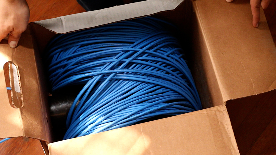
Here’s a demonstration of the difference between balanced and unbalanced connections. Right here, I’ve got 1000 feet of 4-conductor cable, which gives me two pairs to work with.
With a bit of soldering, I can wire one pair to be balanced and the other pair to be unbalanced.
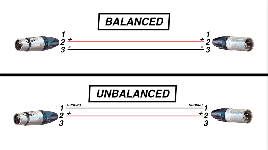
The balanced pair will be wired between pin 2 (+) & 3 (-) of the XLR connectors. The unbalanced pair will be wired between pin 1 (Ground) & 2 (+) of the XLR connectors.
Both connections will therefore be traveling the same path through separate conductor pairs in the 4-conductor cable. That means we can compare the sound quality difference between a 1000 ft. unbalanced cable and a 1000 ft. balanced cable!
Take a listen to this recording to hear the difference. You might be surprised at just how effectively a balanced audio connection can cancel noise!
First, you’ll hear the sound of my voice through an unbalanced connection and then you’ll hear it through a balanced connection.
Keep in mind that the box of wire isn’t especially close any electronic devices. The random RF (radio frequency) noise that surrounds us everywhere we go is generating most of the noise that you hear in the unbalanced recording.
Do I Need Balanced Or Unbalanced Cables?
OK, so 1000 ft. cables might be a little extreme… How important are balanced audio connections in more practical situations?
The truth is that a balanced connection is always superior to an unbalanced connection. However, for cable lengths under 25 to 30 feet, unbalanced cables offer acceptable audio quality for most applications.
If you’re only running a signal over a short distance, you can most likely use unbalanced cables without much worry. For longer cable lengths, it’s well worth it to leverage balanced audio with an XLR or TRS cable.