Whether you work in a recording studio or live production, XLR microphone cables will be a part of your everyday life. XLR cables tend to break over time and they aren’t cheap!
It’s important to know how to make your own cables and repair them when they stop working. In this video, I’m teaching you just that.
What You’ll Need to Make XLR Microphone Cables
In order to make your own XLR cables, you’ll need a few basic tools and materials.
If you have everything you need, feel free to skip ahead to the next section.
Materials
Let’s start with the components of the microphone cable, itself.
XLR Connectors
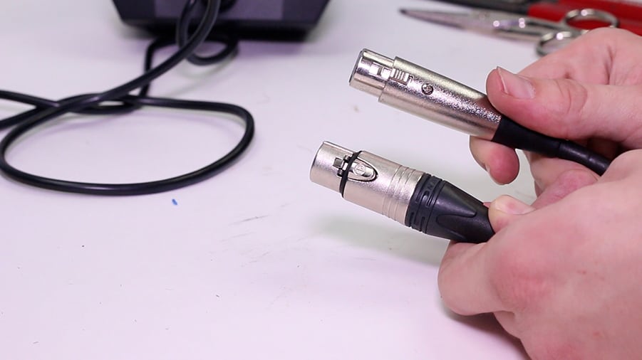
You’ll need two XLR connectors – one male and one female.
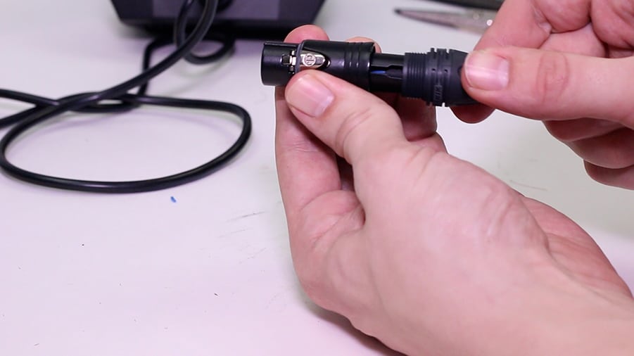
This is the most important component of the cable, so be sure to get Neutrik connectors.
Avoid connectors like the connector on the right at all costs – they get loose over time and are much less rugged than Neutrik-style connectors like the connector on the left.
Bulk Microphone Cable
It’s also important to get a spool of high-quality, production-style cable.
I recommend this bulk microphone cable on Amazon.
Tools
You’ll need a few tools in order to make your own microphone cables. I’ll quickly go over the tools that are needed in this section.
Soldering Iron
The first tool is a soldering iron.
The soldering iron I use is great because it offers a temperature adjustment. If you plan to make and repair your own cables, it’s definitely worth the investment.
However, if you’re on a budget, check out the soldering iron I used when I was first starting out.
Solder
You will also need some solder. There are many types of solder available.
I recommend getting a 60/40 blend solder because it’s easier to work with than lead-free solder.
Choose a solder with close to the same diameter as the wire you’re working with.
Wire Strippers (or Razor Blade)
You don’t necessarily need to have wire strippers, but they will make this process 100 times easier.
Wire strippers allow you to easily remove the jacket from the cable without damaging the components of the cable.
If you don’t have wire strippers like these, you can get by with a pair of scissors or a razor blade. It’s a bit more difficult, and you may need to try a few times if you accidentally cut the shield of the cable.
If you’re using a razor blade or scissors, try to score the jacket of the cable rather than cutting all of the way through. Once it is lightly scored, you’ll be able to tear along those lines to strip away the outer jacket.
Clamp (or Holder)
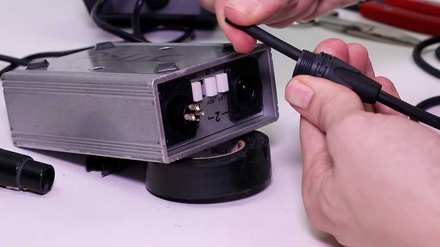
The last thing you’ll need is something to hold your cable in place, because your hands will be occupied by the soldering iron and the solder.
You can use a clamp like this one, but I prefer using an XLR jack to hold it in place.
Don’t use something valuable for this, as it’s possible the heat you’ll apply to the pins could cause damage.
How to Make Your Own XLR Microphone Cable
It doesn’t matter which side you start with – the male connector or the female connector.
I recommend going through the following steps on one side and then following the same steps on the second side.
Step 1: Install Strain Relief Sleeve
The number one mistake beginners make when making XLR cables is forgetting to put on the strain relief sleeve first.
I’ve done it many times, and I’m sure I’ll do it many more times. If you forget this simple step, you’ll need to redo everything at the end.
Step 2: Remove ½-Inch of Jacket from Cable
The second step is to remove the rubber insulator at the end of the cable. Aim to remove about a half-inch off of the end of the cable.
As I mentioned in the previous section, this is really easy with a good pair of wire strippers like these. You can also do it by lightly scoring the rubber jacket with a razor blade and then tearing the jacket away.
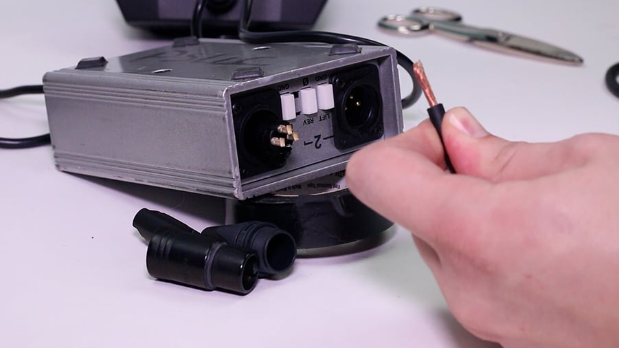
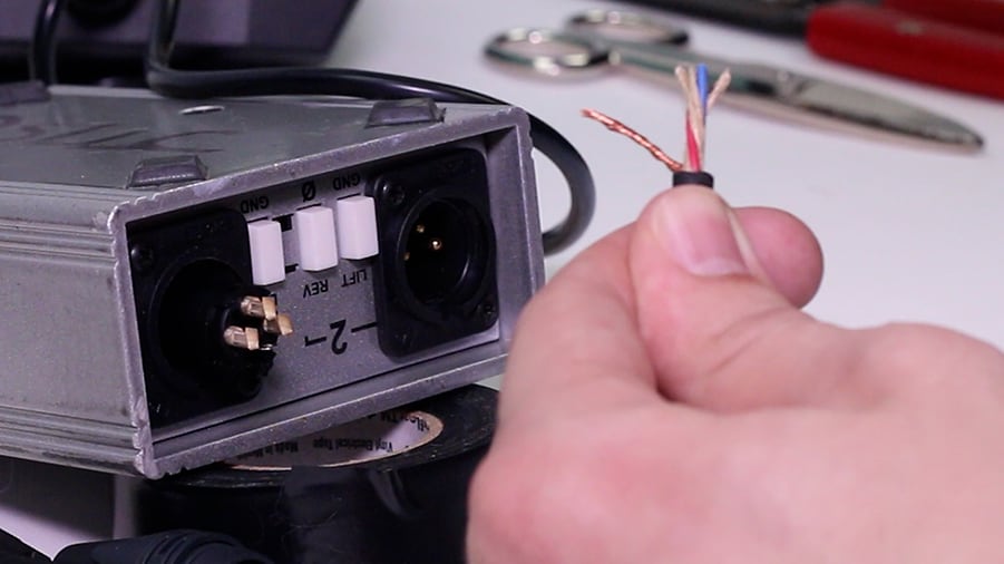
Step 3: Consolidate Shield to One Side
The shield is this outer layer of copper. This is an important part of the cable construction that helps to protect against unwanted noise.
Your cable might be wrapped in strands of copper or it may have a braided shield.
If your cable has a braided shield, use a flathead screwdriver or a pick to separate them from the bottom.
In either case, consolidate the wire strands to one side and twist them into a single group like this.
Step 4: Remove ⅛-Inch of Insulator from Each Conductor
You need to strip away about an ⅛-inch of the insulator on each conductor.
This is where the wire strippers become really useful. If you’re using scissors or a razor blade, be sure not to cut the copper conductor, itself.
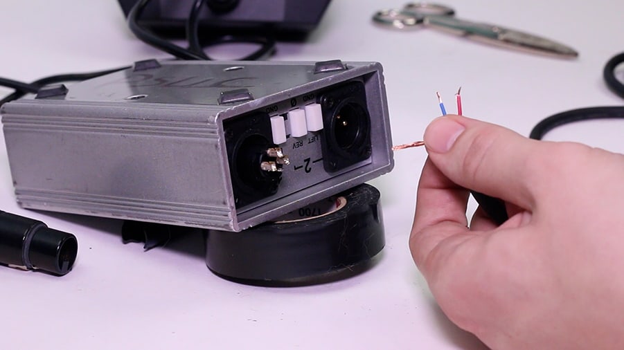
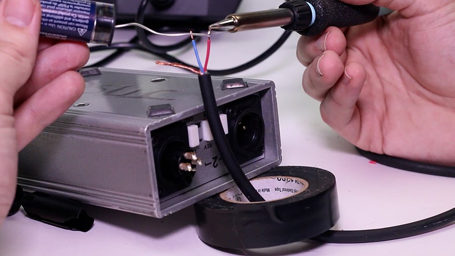
Step 5: Tin the Conductors with Solder
In order to get the best connection between the cable and the connector, you should tin each conductor with some solder. This simply means that you will apply some solder to the tip of each conductor.
I recommend tinning along the entire length of the exposed shield.
It’s best to set your soldering iron to a temperature that allows you to melt the solder by conducting heat through the conductors without touching the soldering iron to the solder, directly.
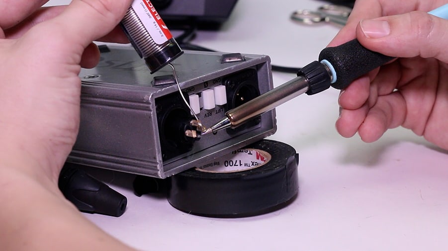
Step 6: Tin the Connector Cups
These connectors have small metal cups for establishing strong connections to the wires.
It’s helpful to tin these cups with solder, as well.
Don’t apply too much, and be sure not to let the solder overflow into the actual connector in a female XLR connector.
Again, It’s best to set your soldering iron to a temperature that allows you to melt the solder by conducting heat through the cups without touching the soldering iron to the solder, directly.
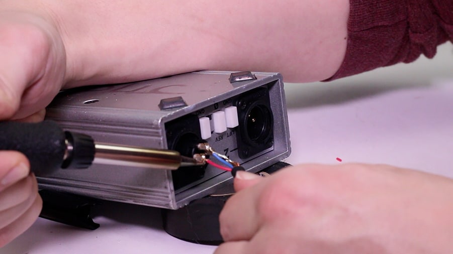
Step 7: Connect the Conductors to the Connector Cups
Finally, it’s time to make the connection between the tinned conductors or your cable and the tinned cups of your connector.
The standard is to connect the shield to Pin 1, the positive wire to Pin 2, and the negative wire to Pin 3.
I like to apply the soldering iron to the cup while holding the conductor to the solder. When the solder in the cup reaches its melting point, the conductor will slide right in. Just hold the conductor in place until the solder hardens.
Step 8: Assemble the Connector
The last step is to assemble the connector.
Slide the collar onto the cable and line it up with the groove in the connector. Tighten the strain relief sleeve to the connector to finish the installation.